Switches are devices that support a large number of ports to connect devices to the network.
Design: Link to heading
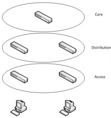
More towards a CCNP or CCDA topic, but designing a network when it comes to the switching side can be done in three building blocks. The access layer, the distribution layer, and the core layer. The access layer generally has a high port density, can support VLANs, QoS, and access lists. The distribution layer will aggregate multiple access layer switches. These are also generally Layer 3 switches to allow routing among an enterprise. It will need to be able to handle the volume of traffic in addition to supporting the same features as the access layer switches. The core layer is the device which will need the highest bandwidth backplane to deal with all of the traffic.
How switches handle traffic: Link to heading
A switch is an intelligent device that can make some decisions on how to handle the data it is given. Switches can be divided into two categories for these decisions: Layer 2 or Layer 3 switches. For the CCNA we will only be interested in the layer 2 switches. Layer 2 switches operate at the data link layer. This layer deals primarily with MAC addresses. A Layer 2 switch will build a CAM table full of dynamically learned MAC addresses. The way it learns these addresses is by inspecting the layer 2 header/trailer and learning the source MAC addresses on the frames it receives. A frame is what a packet is encapsulated in when it moves from device to device across the network.
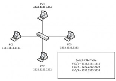
With this example the switch has learned PC1/PC2/and PC3′s MAC addresses. If a packet came in on Fa0/4 from PC4, the switch would look at the source MAC address and put an entry for 4444.4444.4444 on Fa0/4. A switch will route traffic based on this table. There are a few decisions it must make to determine how to handle traffic. When it first receives a frame it will consult it’s CAM table to determine whether or not it has the source MAC address listed for that port. If not, it will add it to the CAM table. In the example above, PC1 sent a frame to the switch, the switch noticed PC1′s MAC address was not in it’s table and added it. The next thing it looks at is the destination MAC address. The CAM table is again consulted. If it finds a match the switch will send the frame directly to the recipient it needs to on whatever port it is on. In the example above, PC1 sends a frame to PC3. Because the switch sees 1111.1111.1111 sending to 3333.3333.3333 and has an entry for 3333.3333.3333 it will send the frame out of port Fa0/3 to the recipient. If a destination is not in the CAM table the switch will need to try to find the recipient. In this case the switch will decide to broadcast the frame out of every port EXCEPT the one it came in on. In this example, PC1 sends a frame destined for PC4. The switch will see a frame from 1111.1111.1111 to 4444.4444.4444. PC4′s MAC address is not in it’s table. The switch will then send the frame out of every port except for Fa0/1 (the source). When PC2 and PC3 get this frame, it will determine if the frame was meant for it, and if not it will ignore it. PC4 will also make the same decision and PC4 will respond. Once PC4 has responded the switch will be able to add PC4′s MAC address to it’s table on Fa0/4.