Going over the basics of network fundamentals and all the models and ideas behind them. The most pushed idea is the OSI networking model which consists of 7 layers, all of which deal with a certain aspect of the networking model.
A P S T N D P
From the top down this represents the following
Layer 7: Application – This layer is the channel between software and external requests. For example, a web server would work with this layer to process HTTP requests.
Layer 6: Presentation – This layer organizes data formats such as JPEG, Text, ASCII, etc
Layer 5: Session – This layer deals with session control; How a conversation should start, function, and end. It can be considered the broken between the layer below and the layers above. It will ensure all the data is proper when being passed up or down.
Layer 4: Transport – This layer is solely focused on data delivery. It deals with many protocols, but most notably it deals with TCP and UDP packets, any checksum errors, and error recovery
Layer 3: Network – This layer deals with logical addressing and routing. It deals with the actual delivery of packets across multiple networks.
Layer 2: Data Link – This layer deals with the rules of how data can be transmitted over a wire such as CSMA/CD and the like. It also deals with encapsulating frames to be transported over a local network
Layer 1: Physical – The actual hardware and electrical signaling to move data over the network. Network cards, cabling, and other hardware are part of this layer
Generic overview of the OSI model above lets work on the idea of some older and modern networks.
Hubs – Devices that simply take a signal and regenerate it out of all ports that are connected.
Switches – Devices that take a signal and make some sort of smart decision to provide a single path from one port to another
Routers – Devices that make decisions based upon higher level information (logical addressing) and will make intelligent decisions on how to handle that data, both incoming and outgoing. Segments networks into two different ones.
Bridge – A device that segments a network in two.
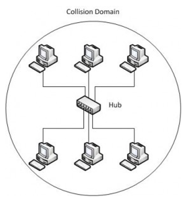
Collision Domain – The bounds where a collision may occur. This is relevant for networks utilizing half-duplex communication and for older devices such as hubs.
Broadcast Domain – The bounds where a broadcast can reach.
Collision Domains: Forgive the visio art, it will get better… hopefully
Every computer connected to that hub is in the collision domain noted by the circle. With a hub, the signal gets sent to every device connected to it, regardless of whether it was meant to go to that machine or not. When the PC at the top left sends information at the same time as the PC on the bottom right, a collision is likely to occur
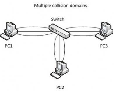
Every computer connected to this switch is limited in its collision domain to the port on the switch and the network card in the PC. The reason being that switches do not just take a signal and send it out of all the ports, it is intelligent enough to be able to send information directly to the PC it needs to. This is further mitigated by the fact that a computer connected to a switch may operate at full-duplex, allowing both simultaneous sending and receiving of information.
Collisions and how they are handled:
The way computers avoid collision in this sense is via something called CSMA/CD or Carrier Sense Multiple Access/Collision Avoidance. The way it works is this, a computer will wait until the line is silent before sending information. Every computer will listen to determine whether the line is truly clear. If two computers were to send at the same time, and a collision were to occur, the computers will immediately trigger a random back off time in which they will not try resending that information until the timer is up.
Unicast vs Broadcast vs Multicast
The idea between these concepts is fairly simple. Unicast deals with a transmission that is intended for one recipient. A broadcast is a transmission that is meant for all recipients that are able to hear it. Multicast is intended for a specific group of recipients.

